LRS
RSP
AD
G3
NSP
SD
SE
HRP
PFC
MSP
ERP
PERIPHERAL
ERDN
UHP

LRS
RSP
AD
G3
NSP
SD
SE
HRP
PFC
MSP
ERP
PERIPHERAL
ERDN
UHP
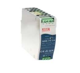
SDR
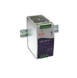
WDR
DUPS
MDR
DRDN
NDR
DDR
TDR
DRC
EDR
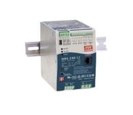
DRS
HDR
DRA
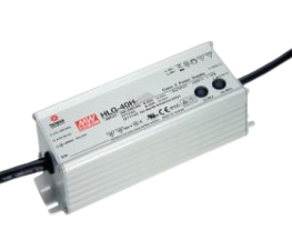
HLG
HBG
ELG
HVG
AP
LPF
XLG
PWM
LPV
GST
SGA
GSM
OWA
GS
NGE
GEM
SGAS
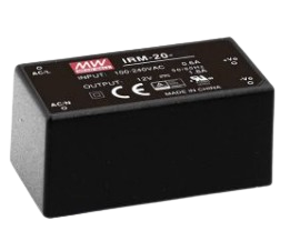
On Board Type
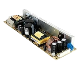
PCB Type
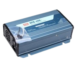
NPB
DRC
ENP
Modified Sine Wave
True Sine Wave
Solar Inverter
AC⇄DC Green Bidirectional Power
VFD
Security & Specific
Programmable Power
Rack Power
Configurable
KNX
LED Accessory
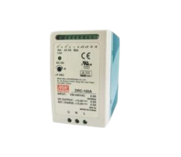
Module Type

DELL

HP
LENOVO
ASUS
ACER

SONY VAIO
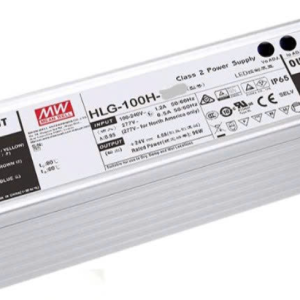
| MODEL | HLG-100H-20 | HLG-100H-24 | HLG-100H-30 | HLG-100H-36 | HLG-100H-42 | HLG-100H-48 | HLG-100H-54 | |
|
OUTPUT |
DC VOLTAGE | 20V | 24V | 30V | 36V | 42V | 48V | 54V |
| CONSTANT CURRENT REGION Note.4 | 10 ~ 20V | 12 ~ 24V | 15 ~ 30V | 18 ~ 36V | 21 ~ 42V | 24 ~ 48V | 27 ~ 54V | |
| RATED CURRENT | 4.8A | 4A | 3.2A | 2.65A | 2.28A | 2A | 1.77A | |
| RATED POWER | 96W | 96W | 96W | 95.4W | 95.76W | 96W | 95.58W | |
| RIPPLE & NOISE (max.) Note.2 | 150mVp-p | 150mVp-p | 200mVp-p | 200mVp-p | 200mVp-p | 200mVp-p | 200mVp-p | |
|
VOLTAGE ADJ. RANGE |
Adjustable for A-Type only (via built-in potentiometer) | |||||||
| 17 ~ 22V | 22 ~ 27V | 27 ~ 33V | 33 ~ 40V | 38 ~ 46V | 43 ~ 53V | 49 ~ 58V | ||
|
CURRENT ADJ. RANGE |
Adjustable for A-Type only (via built-in potentiometer) | |||||||
| 3 ~ 4.8A | 2.5 ~ 4A | 2 ~ 3.2A | 1.65 ~ 2.65A | 1.4 ~ 2.28A | 1.25 ~ 2A | 1.1 ~ 1.77A | ||
| VOLTAGE TOLERANCE Note.3 | ±1.0% | ±1.0% | ±1.0% | ±1.0% | ±1.0% | ±1.0% | ±1.0% | |
| LINE REGULATION | ±0.5% | ±0.5% | ±0.5% | ±0.5% | ±0.5% | ±0.5% | ±0.5% | |
| LOAD REGULATION | ±0.5% | ±0.5% | ±0.5% | ±0.5% | ±0.5% | ±0.5% | ±0.5% | |
| SETUP, RISE TIME Note.6 | 1200ms,50ms/115VAC 500ms,50ms/230VAC | |||||||
| HOLD UP TIME (Typ.) | 16ms / 115VAC, 230VAC | |||||||
|
INPUT |
VOLTAGE RANGE Note.5 |
90 ~ 305VAC 127 ~ 431VDC
(Please refer to “STATIC CHARACTERISTIC” section) |
||||||
| FREQUENCY RANGE | 47 ~ 63Hz | |||||||
|
POWER FACTOR (Typ.) |
PF≧0.98/115VAC, PF≧0.95/230VAC, PF≧0.93/277VAC @ full load
(Please refer to “POWER FACTOR (PF) CHARACTERISTIC” section) |
|||||||
|
TOTAL HARMONIC DISTORTION |
THD< 20% (@ load≧60% / 115VAC,230VAC; @ load≧75% / 277VAC)
(Please refer to “TOTAL HARMONIC DISTORTION (THD)” section) |
|||||||
| EFFICIENCY (Typ.) | 93% | 93% | 93% | 93% | 93% | 93% | 93% | |
| AC CURRENT (Typ.) | 1.2A / 115VAC 0.55A / 230VAC 0.5A / 277VAC | |||||||
| INRUSH CURRENT (Typ.) | COLD START 60A(twidth=415μs measured at 50% Ipeak) at 230VAC; Per NEMA 410 | |||||||
| MAX. No. of PSUs on 16A CIRCUIT BREAKER |
4 units (circuit breaker of type B) / 8 units (circuit breaker of type C) at 230VAC |
|||||||
| LEAKAGE CURRENT | <0.75mA / 277VAC | |||||||
|
PROTECTION |
OVER CURRENT | 95 ~ 106% | ||||||
| Constant current limiting, recovers automatically after fault condition is removed | ||||||||
| SHORT CIRCUIT | Constant current limiting, recovers automatically after fault condition is removed | |||||||
|
OVER VOLTAGE |
23 ~ 27V | 28 ~ 34V | 34 ~ 38V | 41 ~ 46V | 47 ~ 53V | 54 ~ 63V | 59 ~ 65V | |
| Shut down o/p voltage with auto-recovery or re-power on to recovery | ||||||||
| OVER TEMPERATURE | Shut down o/p voltage, recovers automatically after temperature goes down | |||||||
|
ENVIRONMENT |
WORKING TEMP. | Tcase= -40 ~ +80℃ (Please refer to “OUTPUT LOAD vs TEMPERATURE” section) | ||||||
| MAX. CASE TEMP. | Tcase= +80℃ | |||||||
| WORKING HUMIDITY | 20 ~ 95% RH non-condensing | |||||||
| STORAGE TEMP., HUMIDITY | -40 ~ +80℃, 10 ~ 95% RH | |||||||
| TEMP. COEFFICIENT | ±0.03%/℃ (0 ~ 60℃) | |||||||
| VIBRATION | 10 ~ 500Hz, 5G 12min./1cycle, period for 72min. each along X, Y, Z axes | |||||||
|
SAFETY & EMC |
SAFETY STANDARDS Note.8 |
UL8750(type”HL”), CSA C22.2 No. 250.0-08; EN/AS/NZS 61347-1, EN/AS/NZS 61347-2-13 independent; GB19510.1,GB19510.14,
IP65 or IP67, J61347-1, J61347-2-13, EAC TP TC 004 approved ; design refer to UL60950-1, TUV EN60950-1 |
||||||
| WITHSTAND VOLTAGE | I/P-O/P:3.75KVAC I/P-FG:2KVAC O/P-FG:1.5KVAC | |||||||
| ISOLATION RESISTANCE | I/P-O/P, I/P-FG, O/P-FG:100M Ohms / 500VDC / 25℃/ 70% RH | |||||||
| EMC EMISSION Note.8 | Compliance to EN55015, EN55032 Class B, EN61000-3-2 Class C (@ load≧60%) ; EN61000-3-3,GB17743 and GB17625.1, EAC TP TC 020 | |||||||
| EMC IMMUNITY | Compliance to EN61000-4-2,3,4,5,6,8,11, EN61547, EN55024, light industry level (surge immunity Line-Earth 4KV, Line-Line 2KV), EAC TP TC 020 | |||||||
|
OTHERS |
MTBF | 192.2K hrs min. MIL-HDBK-217F (25℃) | ||||||
| DIMENSION | 220*68*38.8mm (L*W*H) | |||||||
| PACKING | 1.12Kg; 12pcs/14.4Kg/0.8CUFT | |||||||
| NOTE | 1. All parameters NOT specially mentioned are measured at 230VAC input, rated current and 25℃ of ambient temperature.
2. Ripple & noise are measured at 20MHz of bandwidth by using a 12″ twisted pair-wire terminated with a 0.1uf & 47uf parallel capacitor. 3. Tolerance : includes set up tolerance, line regulation and load regulation. 4. Please refer to “DRIVING METHODS OF LED MODULE”. 5. De-rating may be needed under low input voltages. Please refer to “STATIC CHARACTERISTIC” sections for details. 6. Length of set up time is measured at first cold start. Turning ON/OFF the driver may lead to increase of the set up time. 7. The driver is considered as a component that will be operated in combination with final equipment. Since EMC performance will be affected by the complete installation, the final equipment manufacturers must re-qualify EMC Directive on the complete installation again. 8.To fulfill requirements of the latest ErP regulation for lighting fixtures, this LED driver can only be used behind a switch without permanently connected to the mains. 9. This series meets the typical life expectancy of >62,000 hours of operation when Tcase, particularly tc point (or TMP, per DLC), is about 80℃ or less. 10. Please refer to the warranty statement on MEAN WELL’s website at http://www.meanwell.com |
|||||||
– Address: 1A Welfare Parade Ashburton VIC, 3147Australia
– Phone: +61398853030
– Email: meanwell168@gmail.com
– Website: https://meanwellaustralia.au/
| Voltage Required | 3.3V, 5V, 12V, 15V, 24V, 27V, 36V, 48V |
|---|

Reviews
There are no reviews yet.